Simple Rankine Cycle
|
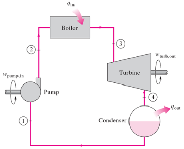
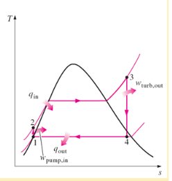
The Simple Rankine Cycle improves the amount work done by superheating the fluid going into the turbine and completely condensing the liquid in the condenser. The Phase diagram above for the ideal cycle also tells us that lowering the minimum pressure will increase the work out. In a real cycle the processes at the pump and turbine are not isentropic and the efficiency of the turbine and pump determine the increase in enthalpy and entropy of the fluid. Below is a sample of the hand calculations for the properties of the system at each node:
|
|
Table 1: Simple Rankine Cycle Results
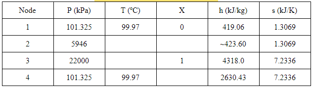
X4 = (7.2336 - 1.3069)/6.0476 = 0.980
h4 = 419.06 + (0.980)(2256.5) = 2630.43 WT = h3 - h4 = 1687.57 WP = h2 - h1 = 4.54 QB = h3 - h2 = 3894.4 Eta = (WT - WP) / QB = 0.432 = 43.2% |
|
For the calculations made, the given values were applied, such as the temperatures, pressures, and the quality-- which can be taken from the vapor dome-- the node being outside of the left side of the dome giving a value of zero, and a value of one for being on the outside of the right side of the dome. Knowing those values, the enthalpy and entropy for those nodes can be found in the thermodynamics tables. Knowing that some nodes share the same entropy, this can be used to calculate quality which allows for other values to be calculated-- such as the enthalpy.
For the simple Rankine cycle, the required heat can be found between nodes 2 and 3; the waste heat can be found between nodes 4 and 1; the work done by the turbine is between nodes 3 and 4--where the turbine is located. The work input is where the pump is located, nodes 1 and 2.
For the simple Rankine cycle, the required heat can be found between nodes 2 and 3; the waste heat can be found between nodes 4 and 1; the work done by the turbine is between nodes 3 and 4--where the turbine is located. The work input is where the pump is located, nodes 1 and 2.
Modified High/Low Pressure Turbine
|
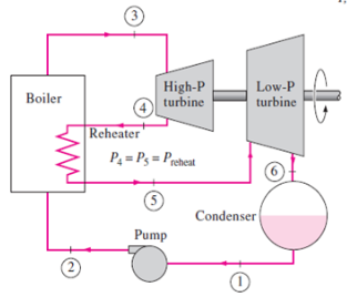
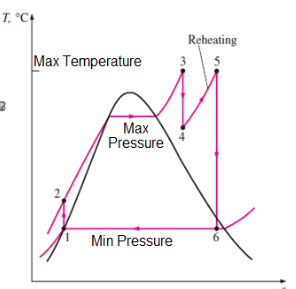
The modified High/Low Pressure Turbine adds a reheater and second turbine to the Simple Rankine cycle to increase the efficiency and power output. This is accomplished by reheating the fluid from the outlet of the first turbine before condensing it. By reheating the outlet fluid of the first turbine the area in the cycle diagram is increased without having to increase the max temperature of the system. While this cycle will always perform better than the Simple Rankine Cycle, it increases the cost of the system due to the need for a second turbine. Below is a sample of the hand calculations for the properties of the system at each node:
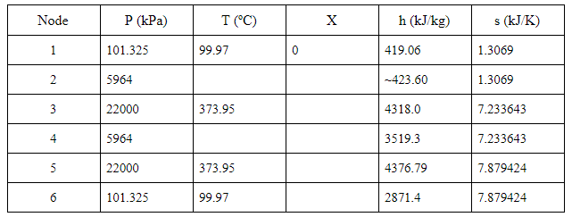
Table 2: Results for High/Low Pressure Turbine
|
|
|
X4 = (7.233 - 3.0221)/2.8723 = 1.466
h4 = 1210.7 + (1.466)(1574.5) = 3519.3 X6 = (7.879 - 1.3069)/6.0476 = 1.087 h6 = 419.06 + (1.087)(2256.5) = 2871.4 |
WT = (h3-h4) + (h5-h6) = 2304.09
WP = h2-h1 = 4.54 QB = (h3-h2)+(h5-h4) = 4751.89 Eta = (WT-WP)/QB = 0.484 = 48.4% |
Similarly with the high/low pressure system, the given values were applied as well as the quality in order to calculate the enthalpies and entropies of each node. The calculations to solve for quality was done in node 4, as it shares the same entropy with node 3. This allows for the enthalpie to be calculated. The same is done for node 6. In order to calculate the heat required, the heat between nodes 3 and 2, and nodes 5 and 4 must be calculated first and then summated. This is because between both nodes, the gas enters the boiler, which determines the required amount of heat needed. The work of the turbine is also calculated by a summation as there are two turbines, one being low pressure and the other being high. The work is calculated by determining the work between nodes 4 and 3, and nodes 6 and 5. Since there is only one pump, which is between nodes 1 and 2, the pump work is only calculated using the enthalpy of those nodes.
Modified Closed Feedwater Heater
|
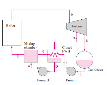
The Modified Closed Feed Water Heater utilizes a heat exchanger and mixing chamber to increase the temperature and enthalpy of the fluid at the inlet of the boiler. This increases efficiency by decreasing the amount of heat the boiler needs to provide to get the fluid to the max temperature. The heat exchanger transfers heat to the condensate from the but the fluids do not come in contact. The main benefit is that a closed force water heater can reduce the amount of pumps needed, because the streams can have independent pressures. This can significantly decrease the cost of the system. Below is a sample of the hand calculations for the properties of the system at each node:
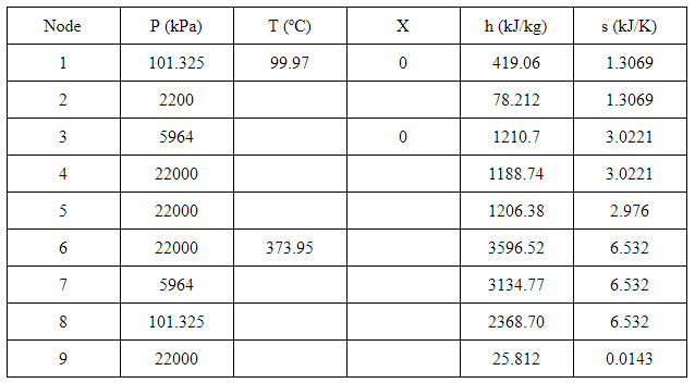
Table 3: Results for a Modified Closed Feedwater Heater
|
|
|
X2 = (1.3069 - 4.2942)/0.2496 = -11.968
h2 = 2011.1 + (-11.968)(161.5) = 78.212 X4 = (3.0221 - 4.2942)/0.2496 = 15.097 h4 = 2011.1 + (-5.097)(161.5) = 1188.742 X7 = (6.532 - 3.0221)/2.8723 = 1.222 h7 = 1210.7 + (1.222)(1574.5) = 3134.77 |
X8 = (6.532 - 1.3069)/6.0476 = 0.864
h8 = 419.06 + (0.864(2256.5) = 2368.703 y = (h3 - h2)/(h6 - h2) = 0.322 WT = y(h6 - h7) + (1-y)(h6 - h8) = 981.162 WP = (1-y)(h2-h1)+(h4-h3)y = 1633.84 QB = h6-h5 = 2390.12 Eta = (WT - WP)/QB = 0.273 = 27.3% |
For the modified closed water heater, there are nine nodes in total and a splitting factor needed to be accounted for. The splitting factor is denoted by ‘y’, and calculated from nodes 2 and 3, and nodes 2 and 6. This is calculated to determine the fraction of steam extracted from the turbine and used to determine the required work in the system. In the closed feedwater heater, there is no mixing of steam and allows the two different steams to vary at different pressures. The heat required can be found between node 6 and 5, where the boiler is located. As for the work, the work done in the turbine is found between nodes 7 and 6, and nodes 6 and 8. This turbine splits from node 6 to the two other nodes, 7 and 8, which is why the difference must be accounted for. The work done in the pump is the summation of the work done in the two individual pumps. For both works, the splitting factor is taken into account, as the nodes connect to the closed water feed.
Modified Open Feedwater Heater
|
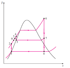
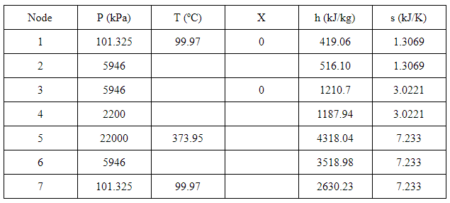
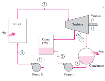
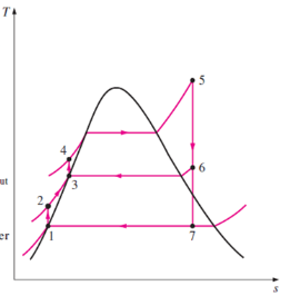
The Modified Open Feedwater Heater utilizes a mixing chamber to increase the temperature and enthalpy of the condensate before introducing it to the boiler similar to the Closed Feedwater Heater. The main difference is that the heat exchange occurs in a mixing chamber where the condensate and steam from the outlet of the turbine come in direct contact. This increases the efficiency of the heat exchange, but the amount of pumps needed may increase due to the steam dropping in pressure. Below is a sample of the hand calculations for the properties of the system at each node.
Table 4: Results for Modified Open Feedwater Heater
|
|
|
X2 = (1.3069 - 1.4337)/5.7894 = 0.022
h2 = 467.13 + (0.022)(2226) = 516.102 X4 = (3.0221 - 4.2942)/0.2496 = -5.097 h4 = 467.13 + (-5.097)(161.5) = 1187.94 X6 = (7.233 - 3.0221)/2.8723 =1.466 h6 = 1210.7 + (1.466)(1574.5) = 3518.976 X7 = (7.233 - 1.3069)/6.0476 = 0.9799 h7 = 419.06 + (0.9799)(2256.5) = 2630.23 |
y = (h3-h2)/(h6-h2) = 0.231 WT = (h5 - h6)+(1-y)(h5-h7) = 1482.51 WP = (1-y)(h2-h1) + (h4 - h3) = 51.675 Qb = h5-h4 = 3130.11 Eta = (WT - WP)/Qb = 0.457 = 45.7% |
In the modified open water heater, the splitting factor must also be calculated. The open water heater is found between nodes 2 and 3, and nodes 2 and 6, which are used for the calculations. This variable is then applied to calculate for the work required, as it did for the closed feed water system. While the calculations are similar, in terms of equations used, the difference between the two factors would be is the lack of a mixing chamber in the open feedwater heater. The open system allows for the gases to mix within the heater, whereas the closed system allows for a separation before entering the mixing chamber. There is less work required in an open system due to the lower pressure.
